Relay: installation; bistable, impulse; ZAMEL

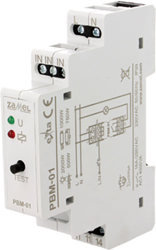
| Type of relay | installation |
| Mounting | for DIN rail mounting |
| Leads | screw terminals |
| Switching method* | OFF-ON |
| Switched voltage | max. 250V AC |
| IP rating | IP20 |
| Manufacturer | ZAMEL |
| Variant | bistable, impulse |
| Manufacturer series | PBM |
* the position in bracket indicates momentary position.
| Symbol | Ucoil | Usup | Usup | Max. operating current | Schematic diagram |
|---|---|---|---|---|---|
| [V AC] | [V DC] | [A] | |||
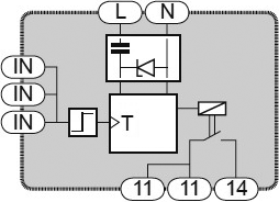
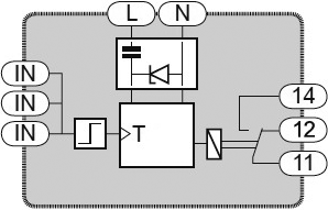
| PBM-01 | 230V AC | - | - | 16 | Fig. 1. |
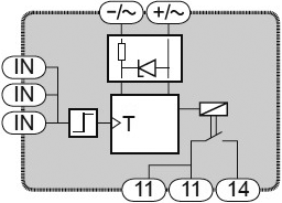
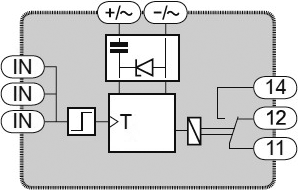
| PBM-01/24V | 24V AC, 24V DC | - | - | 16 | Fig. 2. |
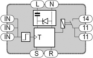
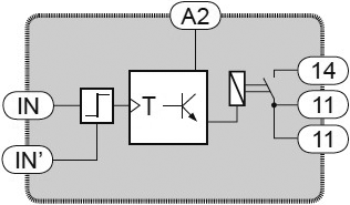
| PBM-02 | 230V AC | - | - | 16 | Fig. 3. |
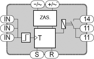
| PBM-02/24V | 24V AC, 24V DC | - | - | 16 | Fig. 4. |
| PBM-03 | 230V AC | - | - | 16 | Fig. 5. |
| PBM-03/24V | 24V AC, 24V DC | - | - | 16 | Fig. 6. |
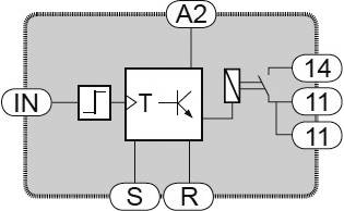
| PBM-04/U | - | 12...230 | 12...230 | 10 | Fig. 7. |
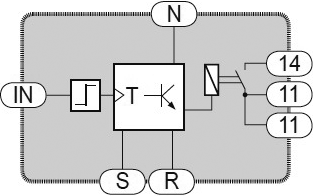
| PBM-05 | 230V AC | - | - | 10 | Fig. 8. |
| PBM-05/12-24V | - | 12...24 | 12...24 | 10 | Fig. 9. |
| PBM-06 | 230V AC | - | - | 16 | - |
| PBM-07 | 230V AC | - | - | 16 | - |
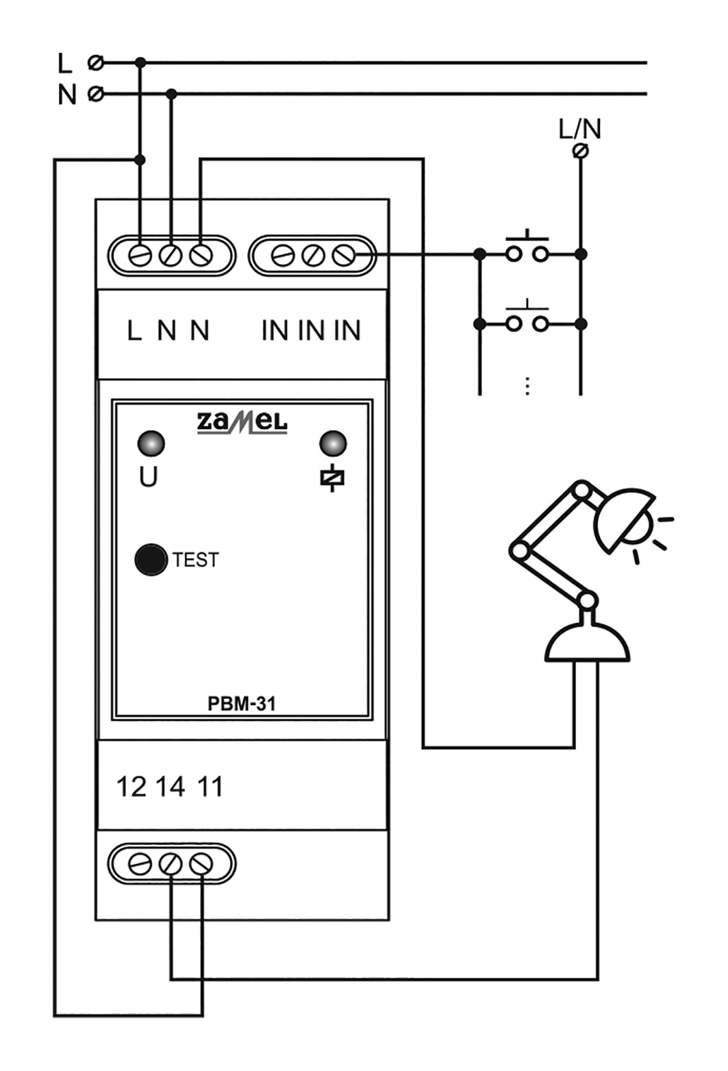
| PBM-31 | 230V AC | - | - | 16 | Fig. 10. |
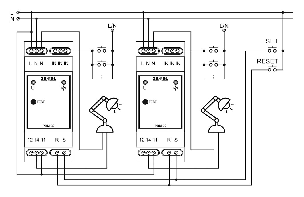
| PBM-32 | 230V AC | - | - | 16 | Fig. 11. |
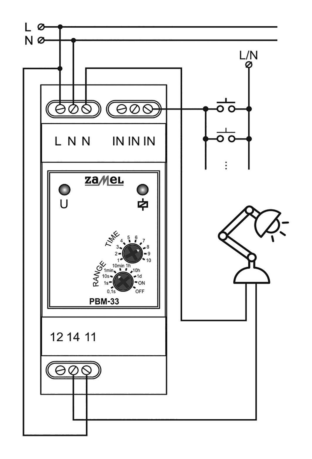
| PBM-33 | 230V AC | - | - | 16 | Fig. 12. |
| Symbol | Body dimensions | Operating temperature | Contacts layout | Features | Indication | Counting range | The additional control inputs |
|---|---|---|---|---|---|---|---|
| [mm] | [°C] | ||||||
| PBM-01 | 90x17.5x66 | -20...45 | NO | remote control | LED | - | - |
| PBM-01/24V | 90x17.5x66 | -20...45 | NO | remote control | LED | - | - |
| PBM-02 | 90x17.5x66 | -20...45 | NO | remote control | LED | - | - |
| PBM-02/24V | 90x17.5x66 | -20...45 | NO | remote control | LED | - | - |
| PBM-03 | 90x17.5x66 | -20...45 | NO | timer; remote control | LED | 0,1s...10days | - |
| PBM-03/24V | 90x17.5x66 | -20...45 | NO | timer; remote control | LED | 0,1s...10days | - |
| PBM-04/U | 90x17.5x66 | -20...45 | NO | relay state memory; remote control | - | - | - |
| PBM-05 | 90x17.5x66 | -20...45 | NO | relay state memory; remote control | - | - | - |
| PBM-05/12-24V | 90x17.5x66 | -20...45 | NO | relay state memory; remote control | - | - | - |
| PBM-06 | 90x17.5x66 | -20...45 | SPDT x2 | remote control | LED | - | - |
| PBM-07 | 90x17.5x66 | -20...45 | SPDT x2 | remote control | LED | - | - |
| PBM-31 | 90x35x66 | -20...60 | NO/NC | zero voltage switching | LED | - | - |
| PBM-32 | 90x35x66 | -20...45 | NO/NC | relay state memory; zero voltage switching | LED | - | RESET, SET |
| PBM-33 | 90x35x66 | -20...60 | NO/NC | timer; zero voltage switching | LED | 0,1s...10days | - |