Type of meter: manometer; Manufacturer: WIKA; Measurement: pressure
| Manufacturer | WIKA |
| Type of meter | manometer |
| Measurement | pressure |
| Application | for gaseous and liquid media that are not highly viscous or crystallising and will not attack copper alloy parts, for measuring points with high dynamic pressure loads or vibrations, hydraulics, compressors |
| Operating temperature | -20...60°C |
| Enclosure material | steel |
| IP rating | IP65 |
| Manufacturer series | 113.53 |
| Kind of meter | analogue, with Bourdon tube |
| Symbol | Accuracy class | Press. meas. range | Manufacturer's part number | Connection | Dimensions | Features | Diameter |
|---|---|---|---|---|---|---|---|
| [bar] | [mm] | ||||||
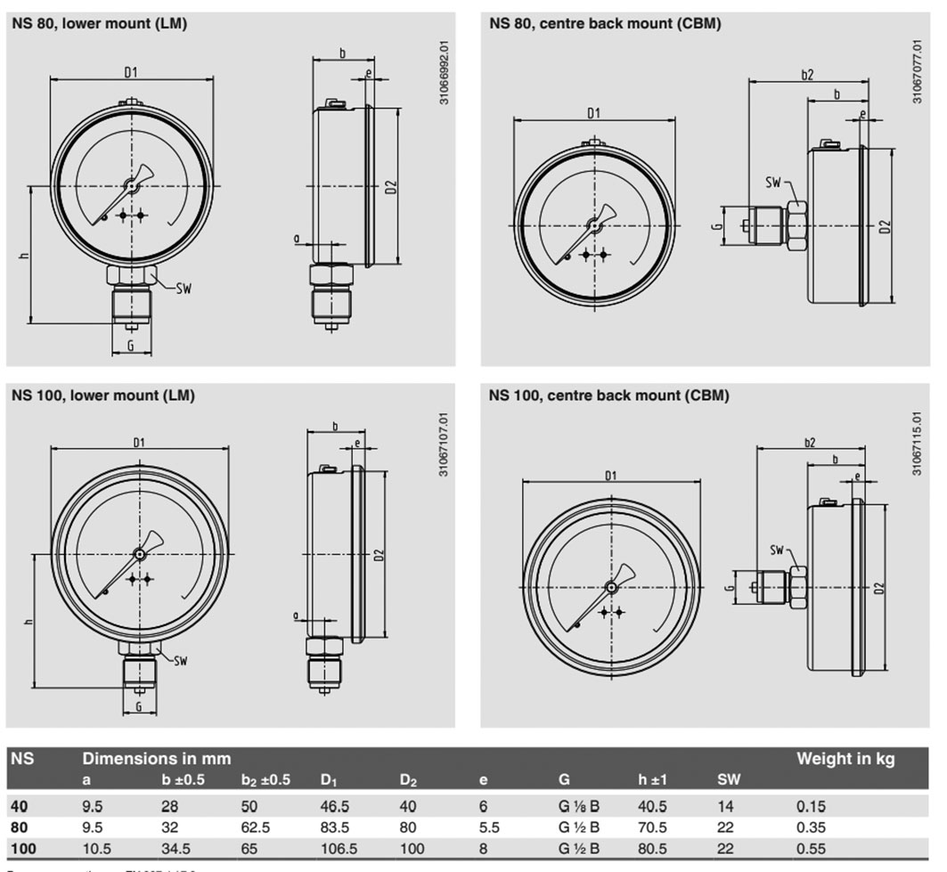
| 113.53.7079660 | 1.6 | 0...160 | 7079660 | M20 x 1,5 | Fig. 1. | lower position of the sensor | 100 |
| 113.53-12195066 | 2.5 | 0...16 | 12195066 | M20 x 1,5 | Fig. 1. | rear position of the sensor | 100 |
| 113.53-13113275 | 2.5 | 0...1 | 13113275 | M20 x 1,5 | Fig. 1. | rear position of the sensor | 100 |
| 113.53-13116088 | 2.5 | 0...4 | 13116088 | M20 x 1,5 | Fig. 1. | rear position of the sensor | 100 |
| 113.53-13156668 | 2.5 | -1...9 | 13156668 | M20 x 1,5 | Fig. 1. | lower position of the sensor | 100 |
| 113.53-30025079 | 2.5 | -1...3 | 30025079 | M20 x 1,5 | Fig. 1. | lower position of the sensor | 100 |
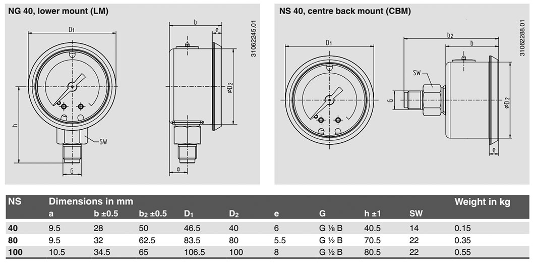
| 113.53-30026920 | 2.5 | 0...40 | 30026920 | M12 x 1,5 | Fig. 2. | rear position of the sensor | 40 |
| 113.53-30036801 | 2.5 | 0...6 | 30036801 | M12 x 1,5 | Fig. 2. | lower position of the sensor | 40 |
| 113.53-30036810 | 2.5 | 0...10 | 30036810 | M12 x 1,5 | Fig. 2. | lower position of the sensor | 40 |
| 113.53-30053382 | 2.5 | 0...16 | 30053382 | M12 x 1,5 | Fig. 2. | rear position of the sensor | 40 |
| 113.53-30073774 | 2.5 | 0...10 | 30073774 | M12 x 1,5 | Fig. 2. | rear position of the sensor | 40 |
| 113.53-30085829 | 2.5 | 0...10 | 30085829 | M20 x 1,5 | Fig. 1. | rear position of the sensor | 100 |
| 113.53-30105111 | 2.5 | 0...60 | 30105111 | M20 x 1,5 | Fig. 1. | rear position of the sensor | 100 |
| 113.53-30107032 | 2.5 | 0...2.5 | 30107032 | M12 x 1,5 | Fig. 2. | lower position of the sensor | 40 |
| 113.53-30124352 | 2.5 | 0...16 | 30124352 | M20 x 1,5 | Fig. 1. | lower position of the sensor | 80 |
| 113.53-30126193 | 2.5 | -1...5 | 30126193 | M20 x 1,5 | Fig. 1. | rear position of the sensor | 100 |
| 113.53-30149061 | 2.5 | 0...6 | 30149061 | M20 x 1,5 | Fig. 1. | rear position of the sensor | 100 |
| 113.53-30163048 | 2.5 | 0...25 | 30163048 | M12 x 1,5 | Fig. 2. | lower position of the sensor | 40 |
| 113.53-30163056 | 2.5 | 0...160 | 30163056 | M12 x 1,5 | Fig. 2. | lower position of the sensor | 40 |
| 113.53-30163064 | 2.5 | 0...250 | 30163064 | M12 x 1,5 | Fig. 2. | lower position of the sensor | 40 |
| 113.53-30170524 | 2.5 | -1...15 | 30170524 | M20 x 1,5 | Fig. 1. | rear position of the sensor | 100 |
| 113.53-30188717 | 2.5 | -1...0 | 30188717 | M20 x 1,5 | Fig. 1. | rear position of the sensor | 100 |
| 113.53-30216800 | 2.5 | 0...100 | 30216800 | M20 x 1,5 | Fig. 1. | rear position of the sensor | 100 |
| 113.53-30226261 | 2.5 | 0...160 | 30226261 | M20 x 1,5 | Fig. 1. | rear position of the sensor | 100 |
| 113.53-30231566 | 2.5 | -1...0 | 30231566 | M12 x 1,5 | Fig. 2. | lower position of the sensor | 40 |
| 113.53-30270073 | 2.5 | 0...400 | 30270073 | M12 x 1,5 | Fig. 2. | lower position of the sensor | 40 |
| 113.53-30271860 | 2.5 | -1...15 | 30271860 | M12 x 1,5 | Fig. 2. | rear position of the sensor | 40 |
| 113.53-30303761 | 2.5 | 0...16 | 30303761 | M12 x 1,5 | Fig. 2. | lower position of the sensor | 40 |
| 113.53-30351472 | 2.5 | 0...25 | 30351472 | M20 x 1,5 | Fig. 1. | rear position of the sensor | 100 |
| 113.53-30427959 | 2.5 | -1...9 | 30427959 | M20 x 1,5 | Fig. 1. | lower position of the sensor | 80 |
| 113.53-30466458 | 2.5 | -1...1.5 | 30466458 | M20 x 1,5 | Fig. 1. | rear position of the sensor | 100 |
| 113.53-30466504 | 2.5 | -1...1.5 | 30466504 | M12 x 1,5 | Fig. 2. | rear position of the sensor | 40 |
| 113.53-30466539 | 2.5 | -1...3 | 30466539 | M12 x 1,5 | Fig. 2. | lower position of the sensor | 40 |
| 113.53-30466601 | 2.5 | -1...5 | 30466601 | M12 x 1,5 | Fig. 2. | lower position of the sensor | 40 |
| 113.53-30466610 | 2.5 | -1...5 | 30466610 | M12 x 1,5 | Fig. 2. | rear position of the sensor | 40 |
| 113.53-30466628 | 2.5 | -1...9 | 30466628 | M20 x 1,5 | Fig. 1. | rear position of the sensor | 100 |
| 113.53-30466652 | 2.5 | -1...9 | 30466652 | M12 x 1,5 | Fig. 2. | lower position of the sensor | 40 |
| 113.53-30466661 | 2.5 | -1...9 | 30466661 | M12 x 1,5 | Fig. 2. | rear position of the sensor | 40 |
| 113.53-30466725 | 2.5 | 0...1 | 30466725 | M12 x 1,5 | Fig. 2. | lower position of the sensor | 40 |
| 113.53-30466733 | 2.5 | 0...1 | 30466733 | M12 x 1,5 | Fig. 2. | rear position of the sensor | 40 |
| 113.53-30466741 | 2.5 | 0...1.6 | 30466741 | M20 x 1,5 | Fig. 1. | rear position of the sensor | 100 |
| 113.53-30466784 | 2.5 | 0...1.6 | 30466784 | M12 x 1,5 | Fig. 2. | lower position of the sensor | 40 |
| 113.53-30466792 | 2.5 | 0...1.6 | 30466792 | M12 x 1,5 | Fig. 2. | rear position of the sensor | 40 |
| 113.53-30466806 | 2.5 | 0...2.5 | 30466806 | M20 x 1,5 | Fig. 1. | rear position of the sensor | 100 |
| 113.53-30466865 | 2.5 | 0...2.5 | 30466865 | M12 x 1,5 | Fig. 2. | rear position of the sensor | 40 |
| 113.53-30466911 | 2.5 | 0...4 | 30466911 | M12 x 1,5 | Fig. 2. | lower position of the sensor | 40 |
| 113.53-30466938 | 2.5 | 0...4 | 30466938 | M12 x 1,5 | Fig. 2. | rear position of the sensor | 40 |
| 113.53-30467021 | 2.5 | 0...6 | 30467021 | M12 x 1,5 | Fig. 2. | rear position of the sensor | 40 |
| 113.53-30467161 | 2.5 | 0...25 | 30467161 | M12 x 1,5 | Fig. 2. | rear position of the sensor | 40 |
| 113.53-30467179 | 2.5 | 0...40 | 30467179 | M20 x 1,5 | Fig. 1. | rear position of the sensor | 100 |
| 113.53-30467241 | 2.5 | 0...40 | 30467241 | M12 x 1,5 | Fig. 2. | lower position of the sensor | 40 |
| 113.53-30467250 | 2.5 | 0...60 | 30467250 | M12 x 1,5 | Fig. 2. | rear position of the sensor | 40 |
| 113.53-30467276 | 2.5 | 0...60 | 30467276 | M12 x 1,5 | Fig. 2. | lower position of the sensor | 40 |
| 113.53-30467306 | 2.5 | 0...100 | 30467306 | M12 x 1,5 | Fig. 2. | rear position of the sensor | 40 |
| 113.53-30467357 | 2.5 | 0...250 | 30467357 | M12 x 1,5 | Fig. 2. | rear position of the sensor | 40 |
| 113.53-30467373 | 2.5 | 0...400 | 30467373 | M12 x 1,5 | Fig. 2. | rear position of the sensor | 40 |
| 113.53-30467438 | 2.5 | 0...40 | 30467438 | M20 x 1,5 | Fig. 1. | rear position of the sensor | 80 |
| 113.53-30467446 | 2.5 | -1...0 | 30467446 | M20 x 1,5 | Fig. 1. | lower position of the sensor | 80 |
| 113.53-30467454 | 2.5 | 0...60 | 30467454 | M20 x 1,5 | Fig. 1. | lower position of the sensor | 80 |
| 113.53-30467462 | 2.5 | 0...60 | 30467462 | M20 x 1,5 | Fig. 1. | rear position of the sensor | 80 |
| 113.53-30467471 | 2.5 | 0...100 | 30467471 | M20 x 1,5 | Fig. 1. | lower position of the sensor | 80 |
| 113.53-30467489 | 2.5 | -1...0 | 30467489 | M20 x 1,5 | Fig. 1. | rear position of the sensor | 80 |
| 113.53-30467497 | 2.5 | 0...100 | 30467497 | M20 x 1,5 | Fig. 1. | rear position of the sensor | 80 |
| 113.53-30467519 | 2.5 | -1...1.5 | 30467519 | M20 x 1,5 | Fig. 1. | rear position of the sensor | 80 |
| 113.53-30467535 | 2.5 | -1...1.5 | 30467535 | M20 x 1,5 | Fig. 1. | lower position of the sensor | 80 |
| 113.53-30467543 | 2.5 | 0...250 | 30467543 | M20 x 1,5 | Fig. 1. | lower position of the sensor | 80 |
| 113.53-30467551 | 2.5 | 0...250 | 30467551 | M20 x 1,5 | Fig. 1. | rear position of the sensor | 80 |
| 113.53-30467641 | 2.5 | -1...9 | 30467641 | M20 x 1,5 | Fig. 1. | rear position of the sensor | 80 |
| 113.53-30467667 | 2.5 | -1...15 | 30467667 | M20 x 1,5 | Fig. 1. | rear position of the sensor | 80 |
| 113.53-30467691 | 2.5 | 0...1 | 30467691 | M20 x 1,5 | Fig. 1. | lower position of the sensor | 80 |
| 113.53-30467756 | 2.5 | 0...1.6 | 30467756 | M20 x 1,5 | Fig. 1. | lower position of the sensor | 80 |
| 113.53-30467799 | 2.5 | 0...2.5 | 30467799 | M20 x 1,5 | Fig. 1. | rear position of the sensor | 80 |
| 113.53-30467802 | 2.5 | 0...2.5 | 30467802 | M20 x 1,5 | Fig. 1. | lower position of the sensor | 80 |
| 113.53-30467837 | 2.5 | 0...4 | 30467837 | M20 x 1,5 | Fig. 1. | lower position of the sensor | 80 |
| 113.53-30467853 | 2.5 | 0...4 | 30467853 | M20 x 1,5 | Fig. 1. | rear position of the sensor | 80 |
| 113.53-30467870 | 2.5 | 0...6 | 30467870 | M20 x 1,5 | Fig. 1. | lower position of the sensor | 80 |
| 113.53-30467888 | 2.5 | 0...6 | 30467888 | M20 x 1,5 | Fig. 1. | rear position of the sensor | 80 |
| 113.53-30467900 | 2.5 | 0...10 | 30467900 | M20 x 1,5 | Fig. 1. | rear position of the sensor | 80 |
| 113.53-30467934 | 2.5 | 0...10 | 30467934 | M20 x 1,5 | Fig. 1. | lower position of the sensor | 80 |
| 113.53-30467969 | 2.5 | 0...16 | 30467969 | M20 x 1,5 | Fig. 1. | rear position of the sensor | 80 |
| 113.53-30467977 | 2.5 | 0...25 | 30467977 | M20 x 1,5 | Fig. 1. | rear position of the sensor | 80 |
| 113.53-30468001 | 2.5 | 0...25 | 30468001 | M20 x 1,5 | Fig. 1. | lower position of the sensor | 80 |
| 113.53-30472741 | 2.5 | -1...3 | 30472741 | M20 x 1,5 | Fig. 1. | rear position of the sensor | 80 |
| 113.53-30472750 | 2.5 | -1...5 | 30472750 | M20 x 1,5 | Fig. 1. | rear position of the sensor | 80 |
| 113.53-30472776 | 2.5 | 0...1 | 30472776 | M20 x 1,5 | Fig. 1. | rear position of the sensor | 80 |
| 113.53-30554951 | 2.5 | 0...60 | 30554951 | M20 x 1 | Fig. 1. | lower position of the sensor | 40 |
| 113.53-31139195 | 2.5 | -1...3 | 31139195 | M20 x 1,5 | Fig. 1. | rear position of the sensor | 100 |
| 113.53-31290655 | 2.5 | 0...160 | 31290655 | G 1/2 B | - | rear position of the sensor | 100 |
| 113.53-7344698 | 2.5 | -1...1.5 | 7344698 | M20 x 1,5 | Fig. 1. | lower position of the sensor | 100 |
| 113.53-7402532 | 2.5 | 0...60 | 7402532 | M20 x 1,5 | Fig. 1. | lower position of the sensor | 100 |
| 113.53-7402558 | 2.5 | 0...4 | 7402558 | M20 x 1,5 | Fig. 1. | lower position of the sensor | 100 |
| 113.53-7402591 | 2.5 | 0...6 | 7402591 | M20 x 1,5 | Fig. 1. | lower position of the sensor | 100 |
| 113.53-7402613 | 2.5 | 0...250 | 7402613 | M20 x 1,5 | Fig. 1. | lower position of the sensor | 100 |
| 113.53-7402639 | 2.5 | 0...10 | 7402639 | M20 x 1,5 | Fig. 1. | lower position of the sensor | 100 |
| 113.53-7402647 | 2.5 | 0...40 | 7402647 | M20 x 1,5 | Fig. 1. | lower position of the sensor | 100 |
| 113.53-7402680 | 2.5 | -1...0 | 7402680 | M20 x 1,5 | Fig. 1. | lower position of the sensor | 100 |
| 113.53-7402702 | 2.5 | 0...1 | 7402702 | M20 x 1,5 | Fig. 1. | lower position of the sensor | 100 |
| 113.53-7421927 | 2.5 | 0...160 | 7421927 | M20 x 1,5 | Fig. 1. | lower position of the sensor | 100 |
| 113.53-7427615 | 2.5 | 0...400 | 7427615 | M20 x 1,5 | Fig. 1. | lower position of the sensor | 100 |
| 113.53-7437025 | 2.5 | 0...16 | 7437025 | M20 x 1,5 | Fig. 1. | lower position of the sensor | 100 |
| 113.53-7438218 | 2.5 | 0...2.5 | 7438218 | M20 x 1,5 | Fig. 1. | lower position of the sensor | 100 |
| 113.53-7443182 | 2.5 | 0...250 | 7443182 | M20 x 1,5 | Fig. 1. | rear position of the sensor | 100 |
| 113.53-7457328 | 2.5 | -1...15 | 7457328 | M20 x 1,5 | Fig. 1. | lower position of the sensor | 100 |
| 113.53-7479411 | 2.5 | -1...5 | 7479411 | M20 x 1,5 | Fig. 1. | lower position of the sensor | 100 |
| 113.53-7549915 | 2.5 | 0...400 | 7549915 | M20 x 1,5 | Fig. 1. | rear position of the sensor | 100 |


