Tachometer in practice – how it works, what it measures, and how to calibrate it
Tachometer in practice – how it works, what it measures, and how to calibrate itDate of publication: 25-03-2026 🕒 12 min read
Is a tachometer just another indicator on a car's dashboard? Not necessarily. In fact, it's one of the key tools used for engine speed monitoring, Actuators diagnostics and process control. If you want to understand what a tachometer really measures and why its readings matter - be sure to read this guide.
Highlights at a glance:
Tachometers are used to measure the rotational speed (RPM) of shafts, motors and rotating components in various equipment.
There are many types of tachometers - mechanical, electronic, contact, non-contact - and their selection depends on the application and operating conditions.
In industry, tachometers act as feedback in Automation systems and support diagnostics and quality control.
Tachometer calibration is possible and, in many industries, required - it ensures that measurements are consistent with standards and metrology standards.
Modern tachometers offer digital functions, data logging capabilities and integration with IIoT systems and predictive maintenance.
Proper RPM measurement increases safety, reduces equipment wear and tear, and optimizes processes.
What is a tachometer?
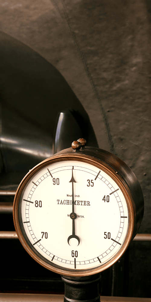
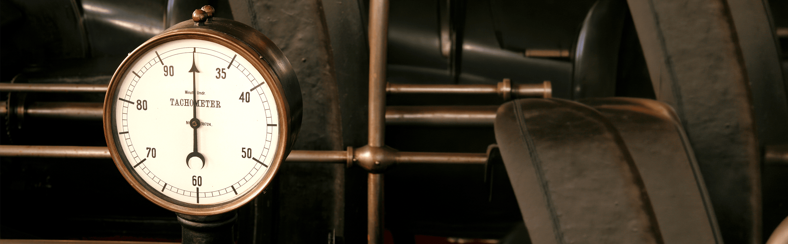
Tachometers are measuring instrument used to measure the rotational speed of rotating elements, most often a shaft or disk, usually in rpm (RPM), less often in Hz. It is found on vehicle dashboards and in control and diagnostic systems for industrial machinery.
Tachometers measure the angular velocity of a shaft, that is, the number of revolutions of the shaft per unit of time. In vehicles, this refers to the rotation of the engine's crankshaft, and in industry to any rotating component, e.g. a spindle, pump or turbine.
Tachometers in the TME catalog
Etymology and history of the tachometer
The name of the device comes from the Greek words táchos meaning "speed" and metron, meaning "measure". In linguistic terms, both tachometer and speedometer mean "speed meter," but in technical practice they refer to other types of speed and different measurements.
The first description of a tachometer was provided by Bryan Donkin in 1810. The first mechanical centrifugal tachometer, on the other hand, is considered to be Dietrich Uhlhorn's design in 1817, and from the 1840s these devices found their way into locomotives, among other applications.
In the Decades that followed, developments swirled from mechanical and electromagnetic systems to electronic and digital solutions used widely in industry today.
Difference between tachometers, speedometers and odometers
In everyday technical practice, we encounter several measuring devices that are easily confused with each other - the tachometer, speedometer and odometer. Although they are all used to monitor traffic parameters, they differ in what specific quantity they measure and for what purpose they are used. To better understand the differences between them, it is useful to put them side by side and look at their functions in practice.
| Instrument | What and how it measures | Units | Signal source | What it tells the operator | Typical environments |
|---|---|---|---|---|---|
| Tachometers | Rotational speed of a rotating component usually expressed in RPM | RPM, Hz | Pulses from Hall Sensors, VR, optical, alternator or ECU | Whether the actuator is operating within a safe and efficient speed range | Vehicles, industrial lines, turbines, pumps, CNC spindles |
| Speedometer | Linear speed of a moving vehicle | km/h, mph | Signal from transmission, ABS, GPS or ECU | How fast the vehicle is moving in traffic | Automotive, general aviation, special vehicles |
| Distance meter | Total distance traveled in units of length | km, miles | Wheels or pulse count converted to distance | What is the total mileage of the vehicle or machine | Automotive, railroad, service and record systems |
By linguistic convention, in automotive we associate a tachometer with engine revolutions and a speedometer with travel speed, although etymologically both names mean a speedometer. In engineering, the names are clarified by the type of quantity measured and the source of the signal.

What is a tachometer used for?
Tachometers are a tool operators, UR technicians and engineers wherever Actuators supervision or quality control tasks arise.
Automotive In vehicles, a tachometer helps keep the engine within a safe speed range, which protects against overheating and excessive wear. On many work machines and tractors, the scale has a green arc for optimum torque and an indication of the speed required for PTO operation. In newer systems, the signal to the indicator comes from the vehicle's control unit (ECU), shaft sensor or alternator.
Industry and Automation
In manufacturing plants, tachometers provide feedback to Actuators and Controllers, stabilizing the speed of conveyors, mixers, pumps and spindles. Critical applications use tachogenerators or non-contact sensors as the source of a precise speed signal for control loops, improving safety and energy efficiency.
Aviation and transportation
In aviation, RPM reading supports maintenance of the cruising range and early detection of deviations in engine operation or rotor speed of the auxiliary power unit (APU). In rail and road transportation, tachometer signals are also used for estimating the speed of movement and counting pulses in control systems, and in survey vehicles to support traffic analysis.
Diagnostics and quality control
Tachometers enable rapid diagnostics of Actuators and verification of process parameters. Handheld models with data logging support trend analysis, i.e., enable analysis of speed changes over time. In industries with stringent quality requirements - such as aerospace, power generation and the food industry - tachometers with documented calibration are particularly important. Accurately maintaining set RPMs reduces downtime and quality errors in production.
How a tachometer works, or the principle of speed measurement
Tachometers determine angular velocity, by counting events that repeat every revolution or by measuring the period between pulses and converting it to frequency. In electronic systems, the basis is a pulse signal from a sensor or ignition system, while in tachometric generators the output voltage is directly proportional to shaft speed. This makes it possible to both show RPM and power control loops in Actuators.
How a tachometer converts a signal into a numerical value
An electronic tachometer takes one of two calculation approaches and matches it to the speed range to get a stable reading:
Frequency counting
It counts the pulses from the sensor in a time window, then determines the RPM from the formula:
RPM = 60 × f[Hz] ÷ PPR
where PPR is the number of pulses per revolution.
Measuring the period
For low RPM, it measures the time between successive pulses and inverts it to the frequency, which improves resolution when running slowly.
Further the signal is sometimes filtered and averaged to smooth the readings, and in panel or vehicle versions, scaled to an analog dial or digital display. In vehicle systems, the source is sometimes the alternator, shaft sensor or ECU, which already provides the processed RPM signal.
Types of tachometers
Tachometers come in many design variants, differing in both the principle of operation and the way the results are measured or presented. Choosing the right type depends on the application, environmental conditions, and requirements for accuracy and reliability. To sort out this variety, it is worth looking at the classification of tachometers according to their method of measurement and form of reading.
Division of tachometers by method of operation
- Mechanical - operation based on the phenomena of classical mechanics. Tachometers of this type most often use centrifugal force or resonant reeds to map rotational speed to the deflection of a spring element or resonance of vibrations. Used historically and in simple systems, today mainly as a curiosity or in specific niches.
- Electromechanical - combine a mechanical drive with an electromagnetic transducer, e.g. eddy current systems like drag-cup. They provide a smooth analog reading and have been widely used in array and aerospace instruments.
- Electronic (digital) - use sensors that generate electrical pulses and digital processing to calculate RPM. They offer accuracy, stability and additional functions such as MIN/MAX memory and data logging.
Division of tachometers by method of measurement
- Contact - Tachometers in which the caster or cone tip is in contact with the component being measured, and the signal comes from an optical encoder or magnetic sensor. They work well at low speeds and when linear speed measurement is also required.
- Non-contact optical and laser - count the transitions of the reflective marker in the sensor beam, which allows to safely measure high RPM and hard-to-reach parts. They are popular in hand-held service meters.
- Non-contact magnetic - Tachometers in which VR and Hall Sensors respond to changes in the magnetic field caused by Wheels teeth or Magnets, generating pulses at a frequency proportional to speed. Hall Sensors work well from very low speeds, VR sensors require signal conditioning at slow speeds.
- Stroboscopic - In these tachometers, matching the flash frequency to the speed "freezes" the image of the marker, allowing reading without contact and without taping, although many models still require a marker (e.g., contrast or reflective). Useful for diagnosing slips and dynamic phenomena.
Division of tachometers by reading method
- Analog - needle display or analog voltage proportional to speed gives a quick, intuitive view of trends and works well with classic control loops.
- Digital - LCD or LED displays present a numerical RPM value, often with averaging and event memory functions. They are now the standard in service and Automation.
Tachometers in industrial practice
In industrial applications, tachometers play a much broader role than simply indicating the current RPM. They are an important part of Automation systems, machine condition monitoring and process quality control. Their functionality and reliability directly affect production efficiency, safety and continuity of work.
Applications and examples of use in Others industries
Production line
On manufacturing lines, Tachometers stabilize the speeds of conveyors, rollers and spindles to maintain consistent process timing and repeatable quality. RPM data goes to Actuators' regulators, which correct RPMs for load changes, reducing material losses and downtime. In practice, optical or magnetic sensors and trend recording are used for predictive maintenance.
Power generation and turbines
In steam and gas turbines, rotor speed is a safety parameter. Tachometers and tachogenerators provide signals for monitoring systems and overdrive shutdowns, and their accuracy and regular calibration are part of the quality policy in critical installations. In industrial practice, non-contact systems with high environmental resistance and data recording for auditing are used.
HVAC and ventilation systems
In fans, blowers and compressors, RPM measurement helps maintain the required flow rate while minimizing energy consumption. Hand-held laser tachometers are useful for quick verification of settings during commissioning and maintenance, and the speed signal can be used in building automation for adaptive capacity control.
Testing of motors and rotating machinery
On dynamometers and test stands, tachometers provide reference RPM for mapping torque and power characteristics, as well as for evaluating speed-dependent vibrations. Depending on the facility, a non-contact, contact or stroboscopic measurement method is chosen to provide a reliable signal at high rpm and varying conditions. In aviation and transportation, RPM data supports acceptance testing of propulsion systems and validation of safety procedures.
In each of these industries, it is crucial to select the right measurement technology and ensure metrological consistency through regular calibration of equipment.
Impulse Counters with Tachometer Function
Tachometers as part of an automation system
Feedback in PID/VFD systems
Tachometers provide the controller with information about the current RPM so that the PID loop can compensate for load changes and maintain the set speed. In Actuators with a frequency converter, the speed signal is sometimes a reference source for the controller, which stabilizes the operation of conveyors, pumps or spindles and reduces fluctuations in process quality. In VFD environments, signal integrity is important, as well as shielding and proper routing of cable masses to minimize EMI interference and provide a reliable reading for the controller.
The role of tachogenerators
AC/DC tachogenerators convert shaft speed into a voltage or current proportional to RPM, resulting in a smooth analog signal ideal for closed-loop and oscillation damping in classical control systems. DC versions reverse polarity as the direction changes, so one transducer can simultaneously signal speed and direction of rotation. These solutions are valued in legacy Actuators and special applications and as an independent, rugged feedback signal source.
What a tachometer should indicate under typical conditions
Passenger car
At idle, typical values are usually in the range of about 600-1000RPM, depending on engine design and condition. While driving, the readings change with load and gear ratio, and the driver should avoid the red field area, which indicates the range that threatens to damage the drive unit. In modern vehicles, an electronic speed limiter is an additional safeguard.
Industrial machinery
Operating ranges vary widely and depend on the process and the design of the Actuators. Slow-speed agitators can operate at tens of RPM, machine tool spindles reach tens of thousands of RPM, and special tools much more. For asynchronous motors, the reference is the synchronous speed determined by the formula:
where:
ns - is the synchronous speed (in revolutions per minute, rpm or RPM). This is the speed at which the rotating magnetic field of the stator moves through the machine.
120 - is a fixed number (resulting from the conversion of 2 half-periods per cycle and 60 seconds per minute).
f - is the frequency of the supply current (in Hertz, Hz). In Europe the standard frequency is usually 50Hz, in North America 60Hz.
p - is the number of pairs of poles in the machine (this is an integer, e.g. 1, 2, 3, etc.), from which the actual speed differs by load-dependent slip.
Fluctuations and irregularities in readings
..., i.e. typical symptoms and causes of failure of tachometers.
- Display "jumps" at constant speedPossible poor electrical contact, defective speed sensor, EMI interference from inverters or too short an averaging window in tachometer electronics. Cables shielding, ferrite blocking reactors and proper ground routing help in installations with VFDs.
- The reading is consistently either under- or overestimated relative to realityThis is a common result of decalibration, incorrect setting of the number of pulses per PPR revolution, or incorrect wheel diameter in contact measurement. Comparison with a reference tachometer or with a strobe and recalibration helps.
- The indication is "frozen" at zero or extreme valuesIt is worth checking the power supply and fuses of the indicator set, the continuity of the signal cables and the condition of the shaft position sensor in automotive and industrial applications.
- Differences between expected RPM and indication with asynchronous ActuatorsFluctuations in process load change slip, so temporary differences are normal. Significant deviations may indicate mechanical slippage, a problem in the drive system or a faulty sensor signal.
In practice, any abnormality is worth confirming with a reference measurement and, if necessary, calibrating according to the plant's quality procedure.
Tachometer diagnostics step by step
- Safety and initial inspection Stop the machine, if necessary, verify safety labels and access to rotating parts. Look at cables, connectors, optical marker, magnetic sensor gap. If in doubt when working on a moving machine, it is advisable to consult a qualified professional.
- Check power supply and continuity Measure the power supply voltage at the IGN and GND terminals and the continuity of the signal cables. Verify fuses and ground points.
- Verify the sensor signal For the alternator, verify the minimum AC voltage required by the indicator. For VR/Hall, evaluate amplitude and pulse shape, remove dust accumulation, set correct gap.
- Comparison with reference instrument Use a handheld laser tachometer or strobe as a reference. If the difference exceeds the accepted threshold, schedule a calibration of the production device.
- Eliminate interference and improve signal quality Apply shielding and separation of cable routes, ferrite chokes on cables, power supply filtration. If necessary, extend the averaging window or change the measurement method from pulse counting to period measurement at low RPM.
- Verify transducer configuration and scaling Verify the PPR setting, the diameter of the contact version wheel, and the mapping of the sensor output to the PLC/controller input. Incorrect parameters result in a consistent display error.
- Service decision If the error persists after corrections, perform calibration at an ISO/IEC 17025-compliant laboratory or have it serviced. Document the results to maintain the metrology path and compliance with quality procedures.This sequence allows you to quickly distinguish equipment failure from installation and signal quality problems, reducing downtime and the risk of erroneous process decisions.
Calibration and measurement accuracy
In industrial applications, calibration of the tachometer is a mandatory practice. Calibration is performed either in an accredited laboratory or in the field using reference standards to confirm the reliability of RPM readings over the entire useful operating range of the device.
What the calibration process looks like
- Definition of check points throughout the operating range.
- Preparation of a speed reference or pulse calibrator and measurement conditions.
- Comparison of the tachometer readings with the standard values and determination of the error.
- Correction of Scales coefficients or PPR parameters, if the design allows it.
- Determination of uncertainty and evaluation of compliance with user requirements.
- Marking the equipment and drawing up a certificate with a full metrological path.
Industry requirements
- Laboratory accreditation to ISO/IEC 17025 to guarantee competence and repeatability of results.
- Measurement consistency to government standards NIST traceability or SI equivalents.
- Complete, audited calibration and service history records maintained in the quality system.
Tachometers accuracy
- Hand-held non-contact optical tachometers typically reach accuracy of about ±0.02...0.05% of the reading when measurement conditions are met.
- The best modern non-contact solutions in precision applications reach about ±0.01% of indication.
- In some regulated applications, e.g. aeronautical drag-cup eddy current tachometers, the required accuracy can be about ±4% over a specified through range (the indicated value is for light aviation).
In factory practice, it is comparison with a reference instrument and a regular calibration cycle that determine the reliability of RPM data in control systems and product quality.
Modern technologies and trends
Digitization of RPM measurement has transformed the tachometer from a simple indicator to a data node supporting control, analysis and quality. Manufacturers are developing recording and connectivity functions, and integration with industrial platforms makes RPM information part of a broader picture of machine and process status. As a result, it is easier to implement predictive strategies and maintain metrological consistency over the life cycle of equipment.
Digitizing Tachometers
Today's instruments offer numerical readings, MIN/MAX memory and waveform recording, and data can be exported via USB or analog outputs to host systems. Digital processing provides stability and high resolution, which translates into repeatability in production and test applications. Increasingly, panel and handheld devices are acting as trend recorders for process control and quality documentation.
Tachometers in IIoT and Industry 4.0 systems
IIoT solutions integrate speed sensors into SCADA platforms and analytical systems, enabling remote monitoring and correlation of RPM with other process signals. Devices with wireless communication are emerging, as well as smart class sensors with IO interfaces that transmit not only speed, but also contextual parameters needed for control and diagnostics. This architecture increases data availability and reduces response time to changes in state.
Non-contact measurements in harsh environments
Non-contact optical and laser methods allow high speeds to be measured from a safe distance, reducing wear and tear and risk to personnel. Robust magnetic sensors and optical sensors with increased resistance to noise and dirt are growing in importance in applications with heavy environmental loads. The precision of such solutions reaches the level needed to control critical operations in industrial settings.
Predictive maintenance (PdM)
Recorded RPM trends become an input feature for algorithms that detect subtle deviations related to Bearings wear, slippage or Actuators upset. Tachometers' connectivity and data buffering make it easier to build an operational history, and integration with quality systems supports auditable maintenance activities. This moves the speed signal from being an indicator to being a predictor of failure.
Summary
Tachometers, although often underestimated, play a key role in monitoring and controlling the operation of motors, machines and entire technological processes. They make it possible not only to measure speed, but also to react to deviations, prevent failures and optimize the operation of drive systems. Thanks to technological advances, these devices have gained in accuracy, functionality and integration with Automation and IIoT systems. Regardless of the industry, choosing the right type of tachometer and its correct calibration have a direct impact on the quality, safety and efficiency of work. So it is worth knowing their operation, capabilities and limitations - both in the context of diagnostics and modern maintenance.
FAQ - Frequently Asked Questions
What is the difference between a tachometer and a speedometer?
Tachometers measure rotational speed (RPM), while speedometers measure the linear speed of a vehicle (e.g. km/h). Both indicate "speed," but in a completely different sense.
Is a tachometer the same as a speedometer?
No, a tachometer shows rotational speed, while a odometer counts the total distance traveled in units of length.
How to check if a tachometer is defective?
Symptoms include missing readings, unstable readings or erroneous values. Verify the sensor, Cables, power supply and compare with a reference device.
Can the tachometer be calibrated?
Yes, calibration is possible and often required - it is carried out by comparing the tachometer readings with reference values at set points.
How does a digital tachometer work?
It counts the pulses from the sensor in a unit of time, converts them into RPM and displays the result in numerical form.
How does an analog tachometer work?
The pointer deflects in proportion to the voltage or force generated by the rotation, showing the value on a scale.
What advantages does a digital tachometer have?
It provides high accuracy, stable readings and the ability to record data or integrate with Automation systems.
Transfer Multisort Elektronik (TME) is one of the world’s largest global distributors of electronic components, electrotechnical parts, workshop equipment, and industrial automation. The catalog includes over 1,500,000 products from 1,300 leading manufacturers. TME’s modern logistics centers in Łódź and Rzgów (Poland), with a combined area of over 40,000 m², ship nearly 6,000 packages daily to customers in more than 150 countries.
TME also invests in the development of knowledge and skills of young engineers and electronics enthusiasts through the TME Education project, and supports the tech community by organizing the TechMasterEvent series, promoting innovation and experience exchange.