Pin grounding: principle of operation and application
Pin grounding: principle of operation and applicationDate of publication: 09-05-2025 Update date: 10-04-2026 🕒 5 min read
Have you ever wondered, what protects you and the equipment around you from the effects of a failure in the electrical system? Proper grounding plays a key role here, and pin earthing is one of the most commonly used solutions, especially in residential construction. In this article we will explain, what its operation is, where it is used and what to pay attention to, so that it effectively performs its protective function.
- What is a pin earthing system
- Principles of operation of the pin earthing system
- The use of pin grounding
- What to pay attention to during installation
- Advantages and disadvantages of pin grounding
What is a pin ground?
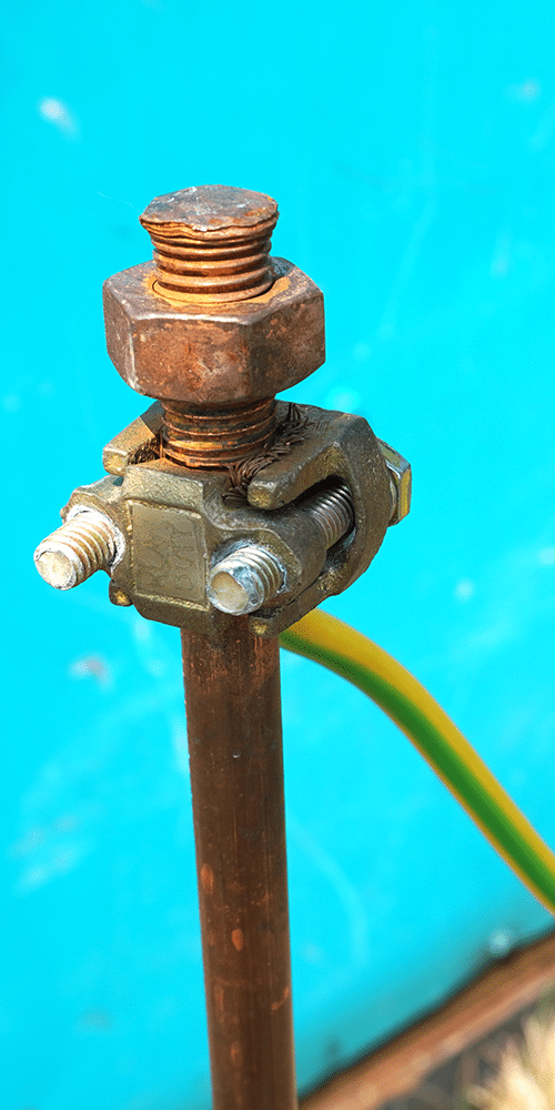
A pin ground is a vertical element or system of elements driven into the ground to achieve an electrical connection to the earth with low resistance. It is most often made of conductive materials, such as copper-plated or galvanized steel. Stud earth electrodes are particularly useful in situations, when making a horizontal grounding or ground loop is difficult. Their fundamental role in electrical installations and grounding systems is to provide a safe path for short-circuit currents to earth.
Construction and materials
The pin earthing system takes the form of a metal rod. For its construction, galvanized steel is most often used, coppered steel or copper. Galvanized steel is relatively inexpensive and provides corrosion protection due to the zinc layer, but may not be as durable as other materials. Copper plated steel has good copper conductivity and corrosion resistance. Copper offers excellent conductivity and corrosion resistance, but can be more expensive.
Principle of operation of a pin grounding system
The pin ground has a key role in grounding systems, providing a direct path for current from the electrical system to the ground. Its primary function is to direct dangerous currents, such as short-circuit or lightning currents, into the ground.
Dissipation of charge
Grounding allows the dissipation of electricity in the ground. When a short circuit or lightning strike occurs, the current flows through the grounding wire to the stud earth, and is then dissipated in the ground due to the large contact area between the rod and the ground.
Grounding resistance
The key parameter characterizing grounding effectiveness is grounding resistance. It is the resistance, that the ground places on the flow of electric current. The lower the resistance to grounding is, the better, because it ensures that the current is dissipated more efficiently into the ground.
Factors affecting the effectiveness of the grounding system
The effectiveness of a grounding electrode depends on a number of factors, that determine its ability to effectively dissipate current. These include:
- Soil type and moisture content are key parameters that affect the resistivity of the soil, and thus on the effectiveness of the grounding system. Soil resistivity is also affected by temperature and mineral content.
- Depth of grounding plunge has a significant effect on grounding resistance. Deeply driven earth electrodes usually reach ground layers with lower resistivity and have a larger contact area, which lowers the resistance.
- Length and diameter of the rod or rods also affect the resistance. Larger diameter and length of the grounding rod or rods increase the contact area with the ground, resulting in lower resistance.
- The possibility of using multiple connected pins to reduce resistance is another important factor. Connecting several grounding pins in parallel lowers the total resistance of the grounding system.
The use of spike grounding
Pin earths are a versatile solution used in many electrical installations. Their ability to effectively dissipate electrical energy in the ground makes them a key element for safety and protection.Pin grounding devices are used in a wide variety of areas:
- Single-family and multi-family housing: pin earthing is commonly used in residential buildings, providing protection against electric shock and surges.
- Small commercial and industrial facilities: these grounding devices are also used in smaller commercial and industrial facilities, where they provide safe grounding of electrical installations.
- Element of lightning protection systems: pin grounding is a key component of lightning protection systems, enabling the safe discharge of lightning energy into the ground.
- Grounding of antenna masts, photovoltaic installations, etc.: pin earthing systems are also used for earthing of antenna masts, photovoltaic installations, etc, photovoltaic installations and other similar structures.
Purpose of the use of earthing systems
The main purpose of using pin grounding is:
- Protection against electric shock (electric shock protection): pin earths provide a safe path for short circuit current to earth, which reduces the risk of electric shock.
- Protection against surges: these earthing rods protect electrical installations and equipment from surges, which can be caused, for example, by. lightning discharges.
- Ensuring proper operation of protection: effective grounding, provided by pin earthing, is essential for the proper operation of protection devices, such as rCD Circuit Breakers.
What to pay attention to when installing?
Proper installation of a pin ground is crucial to ensure the safety and effectiveness of the entire electrical system.
Site selection
An important element is the selection of a suitable installation site. You should consider the type of soil and avoid potential underground obstructions, such as water pipes, gas or sewage pipes. It is recommended to keep an appropriate distance from the walls of the building (minimum 1m) and other installations.
Driving depth
Grounding should be driven to the proper depth, often below the ground frost zone. The minimum depth of driving the vertical grounding often is 3 meters for the lowest part, and the upper part should be at least 0,5m below the ground surface.
Connecting rods
In the case of modular grounding, i.e. consisting of several parts, it is important to connect the rods correctly. Mechanically and electrically strong connections should be provided, using appropriate connectors or welding.
Connection to the installation
The grounding conductor must be permanently and securely connected to the main equalization rail (GSW). The connection is made by means of a grounding conductor and a suitable connector. Care must be taken to ensure, that the connection is resistant to corrosion.
Measurements
After completion of the installation, it is necessary to measure the resistance to grounding. This measurement should be carried out by a certified person. The resistance to grounding should be in accordance with applicable standards.
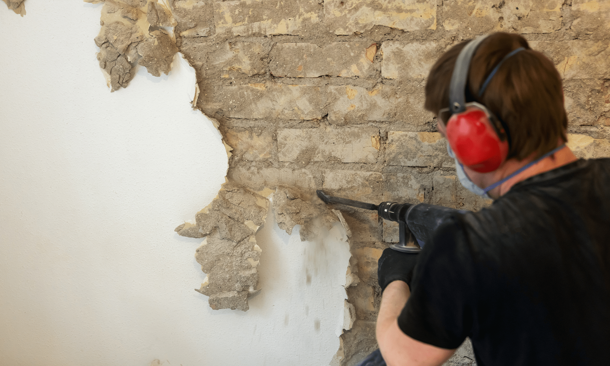
Proper qualification
Work on the grounding system should be carried out by qualified electricians, in accordance with applicable standards and regulations (e.g. PN-EN 62305, IEC 60364). Doing this work yourself can be dangerous.
Advantages and disadvantages of pin grounding
Pin grounding, like any technical solution, have their advantages and disadvantages, that must be taken into account when designing and constructing an earthing system.
Benefits
- Relatively simple and fast installation (hammering).
- Lower cost compared to foundation or perimeter groundings.
- Can be used in existing buildings or in areas with limited space.
- Possibility of deepening by adding more segments (modular grounding).
Disadvantages
- Effectiveness strongly dependent on soil type and moisture content.
- In dry soils, stony or rocky soils, it can be difficult to achieve low resistance and require many deeply driven rods.
- Susceptibility to corrosion (especially of steel grounding).
- The need for periodic inspections and resistance measurements.
Summary, the pin ground plays a key role in ensuring electrical safety, protecting against shock and surges. Its effectiveness depends on proper choice of material, proper installation adapted to ground conditions, and regular inspections. That is why it is so important, to entrust installation and measurement work to qualified specialists.
Bibliography:
- PN Standard-HD 60364-5-54:2011: Specifies requirements for earthing, protective conductors and equipotential bonding conductors.
- PN Standard-EN 62305: A series of standards for lightning protection, including requirements for grounding in lightning protection systems.
- Regulation of the Minister of Infrastructure: Provides general guidelines for electrical installations, including grounding. https://lexlege.pl/tech-war-budynkow/paragraf-184/
Transfer Multisort Elektronik (TME) is one of the world’s largest global distributors of electronic components, electrotechnical parts, workshop equipment, and industrial automation. The catalog includes over 1,500,000 products from 1,300 leading manufacturers. TME’s modern logistics centers in Łódź and Rzgów (Poland), with a combined area of over 40,000 m², ship nearly 6,000 packages daily to customers in more than 150 countries.
TME also invests in the development of knowledge and skills of young engineers and electronics enthusiasts through the TME Education project, and supports the tech community by organizing the TechMasterEvent series, promoting innovation and experience exchange.